Routing Planning Process
Overview
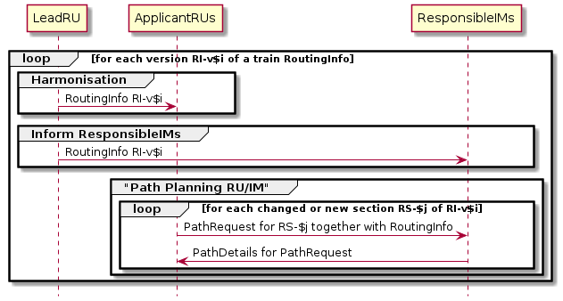
The routing planning process starts with a first version of a RoutingInfo of a train. For each version and each section the Path Planning Process between ApplicantRU and ResponseIM of the section is carried out until the section is completely covered with allocated paths. We use an UML sequence diagram to describe the message flow:
Basis message exchange pattern between involved parties
If in between the participants find out, that a planned version of a RoutingInfo cannot be constructed, a new version is created and communicated by the LeadRU to the ApplicantRUs (Harmonisation). These in turn inform their ResponseIMs with each PathRequest containing also the new version of the RoutingInfo.
The Path Planning Process for each defined section has then to start over again. This must only be done for sections with a new version or totally new sections.
Example: Route Planning of Train Annex 4
The initial planned routing of Train ID1 is shown in Example Train Annex 4.
Planning Process for Version 1
The following messages have to be exchanged by the involved companies to begin the planning process for this train.
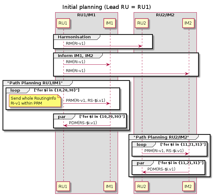
Initial message flow to build path consistent with routing info
For various reasons this process could not be finished. A second RoutingInfo version RI-v2 for the train must now be communicated by the lead RU, which is specified in the next chapter.
RoutingInfo of Example Annex 4 v2
The updated routing info specification describes the planned final status. You can download it here:
../tests/data/train-annex-4-2.yml.
See timetable Example Train Annex 4 Version 2 and Section Graph Version 2.
Look at the section graphs of version 1 and 2 to see the differences:
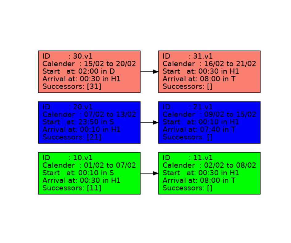
Section graph Annex 4 version 1
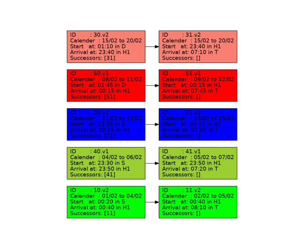
Section graph Annex 4 version 2
As you see, we habe two new routes:
40.v1 -> 41.v1
50.v1 -> 51.v1
and updates for the existing routes which lead to new section versions:
10.v2 -> 11.v2
20.v2 -> 21.v2
30.v2 -> 31.v2
The differences need a new planning process for the updated routing info version 2:
Planning Process for Version 2
The following messages have to be exchanged by the involved companies to reach the state defined by version 2 of the routing info:
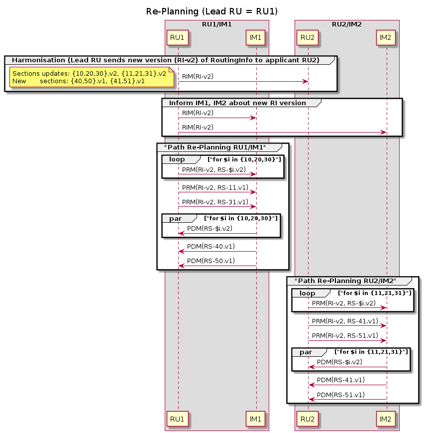
Message flow to build path consistent with routing info version 2
The updated routing info specification describes the planned final status. You can download it here:
../tests/data/train-annex-4-2.yml.
RoutingInformation as TrainInformation
As stated in the JS Sector Handbook chapter 8.2.3.1 the routing info of a train should contain the minimum information of the routes of a train:
The train object first comes into existence at the earliest planning phase when the RA starts to develop plans to run a train. The Lead RU creates the identification for the train at this stage. The Lead RU will then go through a harmonisation process with all RAs involved in the particular business case. They will then apply for paths to run the trains. The attributes of the object Train are:
Train route (geography, journey sections / locations, timing, indication of responsible RU and IM) The locations to be defined for the train route shall be at least:
origin of the train route
border points (Handover points, Interchange points)
destination of train route
Train parameters (weight, length)
Train calendar
Shown here is the minimum requirement from the technical point of view. The technical details of the object Train are given in the XSD structure (see the current TAF/TAP XSD Schema / data catalogue see JSG web site http://taf_jsg.info/) within the element TrainInformation.
With the ECM we propose to fill the TrainInformation with the information contained in the RoutingInformation. The minimum required information is contained in the set of sections. They are mandatory. The routes computed from the sections can also be included in the TrainInformation for information purpose.
Not necessary for the route planning phase are the train parameters (weight, length) as stated in the SHB. A calendar can not be specified for the train but only at the route level.
Download the proposal for a new version 2.x of the XSD here:
../tests/data/xml/taf_cat_complete_sector.xsd.
Have a look at the XSD Element TrainInformation and compare it to new previous version XSD Element TrainInformation 2.2.4.
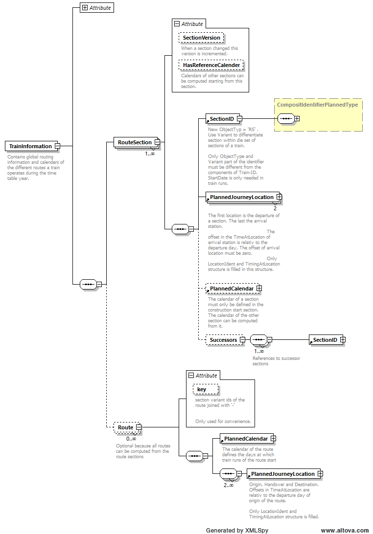
Overview XSD TrainInformation containing Routes and RouteSections
These are the main differences to the original version:
The RouteSection is the main structure that contains the necessary information.
The Route elements can be computed from sections. That is why they are optional. But we propose to transfer them also for informational purpose.
Each section is identified by a new type SectionID which is like the type TrainID but with new ObjectType ‘RS’. The Variant field of SectionID must be unique within the set of sections of a train.
The two version attributes RouteInfoVersion and SectionVersion are optional. We propose them to be used to easily detect the changes in a routing info (see process above).
Each section must have exactly two PlannedJourneyLocations:
First is the departure station
Second is the arrival station of the section
In the PlannedJourneyLocations only these fields are filled:
LocationIdent
TimingAtLocation needs two attributes:
Offset which is set to the number of night shifts between departure and arrival of the section. The offset at the departure station (first location) must always be zero.
Timing contains the departure time for the first location (which is the departure) and or arrival time last location of the section (which is the arrival).
The PlannedCalendar of a section is optional for sections which are not StartOfConstruction. Only these must have a calendar.
The Successors element contains the links to following sections. These links are used to compute all possible routes of the train.
One remark concerning the Timing element of a location: If parties are only interested to communicate the calendars of routes and sections, the element could be filled with a default (for example 0:00 or 12:00). Thus the above mentioned updates must only be communicated if changes occurred in:
Section departure or arrival stations
Section calendar
Offset at arrival station
We have generated the new train information structures for the two version of the example above. See
TrainInformation Example Annex 4 V1 the first version of the example above
TrainInformation Example Annex 4 V2 the update resulting in version 2